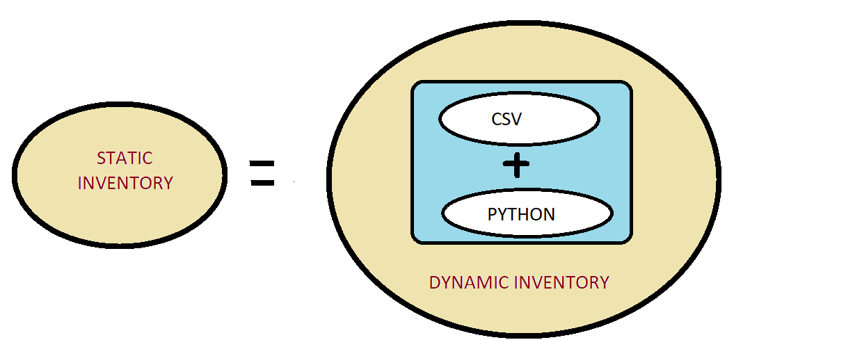
Best Practices of Ansible Role

I have written about Ansible Roles in my career. But when I talk about the “Best Practice of writing an Ansible Role”, half of them were not following the best practices.
When I started writing this blog, I had only limited knowledge of Ansible Roles and about the practices being followed. But reading more on Ansible roles has helped in enhancing my knowledge.
Without the proper understanding of the Architecture of Ansible Role, I was incapable of enjoying all the functionality for writing an Ansible Role. Earlier, I used “command” and “shell” modules for writing an Ansible Role. Here, in this blog, I’ve discussed the best practices of Ansible Role. Let’s
read these in detail.
 

Continue reading “Best Practices of Ansible Role”

Docker Logging Driver

The  docker logs command batch-retrieves logs present at the time of execution. The docker logs command shows information logged by a running container. The docker service logs command shows information logged by all containers participating in a service. The information that is logged and the format of the log depends almost entirely on the container’s endpoint command.

These logs are basically stored at “/var/lib/docker/containers/.log”, So basically it is not easy to use this file by using Filebeat because the file will change every time when the new container is up with a new container id.

So, How to monitor these logs which are formed in different files ? For this Docker logging driver were introduced to monitor the docker logs.

Docker includes multiple logging mechanisms to help you get information from running containers & services. These mechanisms are called logging drivers. These logging drivers are configured for the docker daemon.

To configure the Docker daemon to default to a specific logging driver, set the value of log-driver to the name of the logging driver in the daemon.json file, which is located in /etc/docker/ on Linux hosts or C:\ProgramData\docker\config\ on Windows server hosts.

The default logging driver is json-file. The following example explicitly sets the default logging driver to syslog:

{                                            
  “log-driver”: “syslog”
}

After configuring the log driver in daemon.json file, you can define the log driver & the destination where you want to send the logs for example logstash & fluentd etc. You can define it either on the run time execution command as “–log-driver=syslog –log-opt syslog-address=udp://logstash:5044” or if you are using a docker-compose file then you can define it as:

“`
logging:
driver: fluentd
options:
fluentd-address: “192.168.1.1:24224”
tag: “{{ container_name }}”
“`

Once you have configured the log driver, it will send all the docker logs to the configured destination. And now if you will try to see the docker logs on the terminal using the docker logs command, you will get a msg:

“`
Error response from daemon: configured logging driver does not support reading
“`

Because all the logs have been parsed to the destination.

Let me give you an example that how i configured logging driver fluentd
and parse those logs onto Elasticsearch and viewed them on Kibana. In this case I am configuring the logging driver at the run-time by installing the logging driver plugin inside the fluentd but not in daemon.json. So make sure that your containers are created inside the same docker network where you will be configuring the logging driver.

Step 1: Create a docker network.

“`
docker network create docker-net
“`

Step 2: Create a container for elasticsearch inside a docker network.

“`
docker run -itd –name elasticsearch -p 9200:9200 –network=docker-net elasticsearch:6.4.1
“`

Step 3: Create a fluentd configuration where you will be configuring the logging driver inside the fluent.conf which is further being copied inside the fluentd docker image.

fluent.conf

“`

@type forward
port 24224
bind 0.0.0.0

@type copy

@type elasticsearch
host elasticsearch
port 9200
logstash_format true
logstash_prefix fluentd
logstash_dateformat %Y%m%d
include_tag_key true
type_name access_log
tag_key app
flush_interval 1s
index_name fluentd
type_name fluentd

@type stdout

“`

This will also create an index naming as fluentd & host is defined in the name of the service defined for elasticsearch.

Step 4: Build the fluentd image and create a docker container from that.

Dockerfile.fluent

“`
FROM fluent/fluentd:latest
COPY fluent.conf /fluentd/etc/
RUN [“gem”, “install”, “fluent-plugin-elasticsearch”, “–no-rdoc”, “–no-ri”, “–version”, “1.9.5”]
“`

Here the logging driver pluggin is been installed and configured inside the fluentd.

Now build the docker image. And create a container.

“`
docker build -t fluent -f Dockerfile.fluent .
docker run -itd –name fluentd -p 24224:24224 –network=docker-net fluent
“`

Step 5: Now you need to create a container whose logs you want to see on kibana by configuring it on the run time. In this example, I am creating an nginx container and configuring it for the log driver.

“`
docker run -itd –name nginx -p 80:80 –network=docker-net –log-driver=fluentd –log-opt fluentd-address=udp://:24224 opstree/nginx:server
“`

Step 6: Finally you need to create a docker container for kibana inside the same network.

“`
docker run -itd –name kibana -p 5601:5601 –network=docker-net kibana
“`

Now, You will be able to check the logs for the nginx container on kibana by creating an index fluentd-*.

Types of Logging driver which can be used:

       Driver           Description

  •  none:           No logs are available for the container and docker logs does  not return any output.
  •  json-file:     The logs are formatted as JSON. The default logging driver for Docker.
  •  syslog:     Writes logging messages to the syslog facility. The syslog daemon must be running on the host machine.
  •  journald:     Writes log messages to journald. The journald daemon must be running on the host machine.
  •  gelf:     Writes log messages to a Graylog Extended Log Format (GELF) endpoint such as Graylog or Logstash.
  •  fluentd:     Writes log messages to fluentd (forward input). The fluentd daemon must be running on the host machine.
  •  awslogs:     Writes log messages to Amazon CloudWatch Logs.
  •  splunk:     Writes log messages to splunk using the HTTP Event Collector.
  •  etwlogs:     Writes log messages as Event Tracing for Windows (ETW) events. Only available on Windows platforms.
  •  gcplogs:     Writes log messages to Google Cloud Platform (GCP) Logging.
  •  logentries:     Writes log messages to Rapid7 Logentries.

Prometheus Overview and Setup

Overview

Prometheus is an opensource monitoring solution that gathers time series based numerical data. It is a project which was started by Google’s ex-employees at SoundCloud. 

To monitor your services and infra with Prometheus your service needs to expose an endpoint in the form of port or URL. For example:- {{localhost:9090}}. The endpoint is an HTTP interface that exposes the metrics.

For some platforms such as Kubernetes and skyDNS Prometheus act as directly instrumented software that means you don’t have to install any kind of exporters to monitor these platforms. It can directly monitor by Prometheus.

One of the best thing about Prometheus is that it uses a Time Series Database(TSDB) because of that you can use mathematical operations, queries to analyze them. Prometheus uses SQLite as a database but it keeps the monitoring data in volumes.

Pre-requisites

  • A CentOS 7 or Ubuntu VM
  • A non-root sudo user, preferably one named prometheus

Installing Prometheus Server

First, create a new directory to store all the files you download in this tutorial and move to it.

mkdir /opt/prometheus-setup
cd /opt/prometheus-setup
Create a user named “prometheus”

useradd prometheus

Use wget to download the latest build of the Prometheus server and time-series database from GitHub.


wget https://github.com/prometheus/prometheus/releases/download/v2.0.0/prometheus-2.0.0.linux-amd64.tar.gz
The Prometheus monitoring system consists of several components, each of which needs to be installed separately.

Use tar to extract prometheus-2.0.0.linux-amd64.tar.gz:

tar -xvzf ~/opt/prometheus-setup/prometheus-2.0.0.linux-amd64.tar.gz .
 Place your executable file somewhere in your PATH variable, or add them into a path for easy access.

mv prometheus-2.0.0.linux-amd64  prometheus
sudo mv  prometheus/prometheus  /usr/bin/
sudo chown prometheus:prometheus /usr/bin/prometheus
sudo chown -R prometheus:prometheus /opt/prometheus-setup/
mkdir /etc/prometheus
mv prometheus/prometheus.yml /etc/prometheus/
sudo chown -R prometheus:prometheus /etc/prometheus/
prometheus --version
  

You should see the following message on your screen:

  prometheus,       version 2.0.0 (branch: HEAD, revision: 0a74f98628a0463dddc90528220c94de5032d1a0)
  build user:       root@615b82cb36b6
  build date:       20171108-07:11:59
  go version:       go1.9.2
Create a service for Prometheus 

sudo vi /etc/systemd/system/prometheus.service
[Unit]
Description=Prometheus

[Service]
User=prometheus
ExecStart=/usr/bin/prometheus --config.file /etc/prometheus/prometheus.yml --storage.tsdb.path /opt/prometheus-setup/

[Install]
WantedBy=multi-user.target
systemctl daemon-reload

systemctl start prometheus

systemctl enable prometheus

Installing Node Exporter


Prometheus was developed for the purpose of monitoring web services. In order to monitor the metrics of your server, you should install a tool called Node Exporter. Node Exporter, as its name suggests, exports lots of metrics (such as disk I/O statistics, CPU load, memory usage, network statistics, and more) in a format Prometheus understands. Enter the Downloads directory and use wget to download the latest build of Node Exporter which is available on GitHub.

Node exporter is a binary which is written in go which monitors the resources such as cpu, ram and filesystem. 

wget https://github.com/prometheus/node_exporter/releases/download/v0.15.1/node_exporter-0.15.1.linux-amd64.tar.gz

You can now use the tar command to extract : node_exporter-0.15.1.linux-amd64.tar.gz

tar -xvzf node_exporter-0.15.1.linux-amd64.tar.gz .

mv node_exporter-0.15.1.linux-amd64 node-exporter

Perform this action:-

mv node-exporter/node_exporter /usr/bin/

Running Node Exporter as a Service

Create a user named “prometheus” on the machine on which you are going to create node exporter service.

useradd prometheus

To make it easy to start and stop the Node Exporter, let us now convert it into a service. Use vi or any other text editor to create a unit configuration file called node_exporter.service.


sudo vi /etc/systemd/system/node_exporter.service
This file should contain the path of the node_exporter executable, and also specify which user should run the executable. Accordingly, add the following code:

[Unit]
Description=Node Exporter

[Service]
User=prometheus
ExecStart=/usr/bin/node_exporter

[Install]
WantedBy=default.target

Save the file and exit the text editor. Reload systemd so that it reads the configuration file you just created.


sudo systemctl daemon-reload
At this point, Node Exporter is available as a service which can be managed using the systemctl command. Enable it so that it starts automatically at boot time.

sudo systemctl enable node_exporter.service
You can now either reboot your server or use the following command to start the service manually:
sudo systemctl start node_exporter.service
Once it starts, use a browser to view Node Exporter’s web interface, which is available at http://your_server_ip:9100/metrics. You should see a page with a lot of text:

Starting Prometheus Server with a new node

Before you start Prometheus, you must first edit a configuration file for it called prometheus.yml.

vim /etc/prometheus/prometheus.yml
Copy the following code into the file.

# my global configuration which means it will applicable for all jobs in file
global:
  scrape_interval:     15s # Set the scrape interval to every 15 seconds. Default is every 1 minute. scrape_interval should be provided for scraping data from exporters 
  evaluation_interval: 15s # Evaluate rules every 15 seconds. The default is every 1 minute. Evaluation interval checks at particular time is there any update on alerting rules or not.

# Load rules once and periodically evaluate them according to the global 'evaluation_interval'. Here we will define our rules file path 
#rule_files:
#  - "node_rules.yml"
#  - "db_rules.yml"

# A scrape configuration containing exactly one endpoint to scrape: In the scrape config we can define our job definitions
scrape_configs:
  # The job name is added as a label `job=` to any timeseries scraped from this config.
  - job_name: 'node-exporter'
    # metrics_path defaults to '/metrics'
    # scheme defaults to 'http'. 
    # target are the machine on which exporter are running and exposing data at particular port.
    static_configs:
      - targets: ['localhost:9100']
After adding configuration in prometheus.yml. We should restart the service by

systemctl restart prometheus
This creates a scrape_configs section and defines a job called a node. It includes the URL of your Node Exporter’s web interface in its array of targets. The scrape_interval is set to 15 seconds so that Prometheus scrapes the metrics once every fifteen seconds. You could name your job anything you want, but calling it “node” allows you to use the default console templates of Node Exporter.
Use a browser to visit Prometheus’s homepage available at http://your_server_ip:9090. You’ll see the following homepage. Visit http://your_server_ip:9090/consoles/node.html to access the Node Console and click on your server, localhost:9100, to view its metrics.

Classless Inter Domain Routing Made Easy (Cont..)

Introduction :

As we had a discussion  about Ip addresses and their classes in the previous blog,we can now start with Sub-netting.

Network Mask /Subnet Mask –

As mask means to cover something,
IP Address is made up of two components, One is the network address and the other is the host address.The Ip Address needs to be separated into the network and host address, and this separation of network and host address in done by Subnet Mask.The host part of an IP Address is further divided into subnet and host address if more subnetworks are needed and this can be done by subnetting. It is called as a subnet mask or Network mask as it is used to identify network address of an IP address by performing a bitwise AND operation on the netmask.
Subnet Mask is of 32 Bit and is used to divide the network address and host addresses of an IP.
In a Subnet Mask all the network bits are set to 1’s and all the host bits are set to 0’s.
 
Whenever we see an IP Address – We can easily Identify that
WHAT IS NETWORK PART OF THAT IP
WHAT IS THE HOST PART OF THAT IP
 
FORMAT :
mmmmmmmm.mmmmmmmm.mmmmmmmm.mmmmmmmm
(Either it will have 1 or 0 Continuously)
EXAMPLE :
A Class Network Mask
In Binary : 11111111.00000000.00000000.00000000         – First 8 Bits will be Fixed
In Decimal : 255.0.0.0
Let the IP Given is – 10.10.10.10
When we try to Identify it we know that it belong to class A, So the subnet mask will be : 255.0.0.0
And the Network Address will be : 10.0.0.0
 
B Class Network Mask  
In Binary : 11111111.11111111.00000000.00000000           – First 16 Bits will be Fixed
In Decimal : 255.255.0.0
Let the IP Given is -150.150.150.150
When we try to Identify it we know that it belong to class B, So the subnet mask will be : 255.255.0.0
And the Network Address will be : 150.150.0.0
 
C Class Network Mask  
In Binary : 11111111.111111111.11111111.00000000           – First 32 Bits will be Fixed
In Decimal : 255.255.255.0
Let the IP Given is – 200.10.10.10
When we try to Identify it we know that it belong to class C, So the subnet mask will be : 255.255.255.0
And the Network Address will be : 200.10.10.0

Subnetting :

The method of dividing a network into two or more networks is called subnetting.
A subnetwork, or subnet, is a logically subdivision of an IP network
Subnetting provides Better Security
Smaller collision and Broadcast  Domains
Greater administrative control of each network.
Subnetting – WHY ??
Answer : Shortage of IP Addresses
SOLUTIONS : –
1) SUBNETTING – To divide Bigger network into the smaller networks and to reduce the wastage
2) NAT –  Network Address Translation
3) Classless IP Addressing –
No Bits are reserved for Network and Host
 
**Now the Problem that came is how to Identify the Class of IP Address :**
Let a IP Be : 10.10.10.10
If we talk about classful we can say it is of class A But in classless : We can check it through subnetwork mask.
255.255.255.0
So by this we can say that first 24 bits are masked for network and the left 8 are for host.
Bits Borrowed from Host and added to Network
Network ID(N)
Network ID(N)
Host ID(H)
Host ID(H)
Network ID(N)
Network ID(N)
Subnet
Host ID(H)
Network ID(N)
Network ID(N)
Subnet
Subnet/Host
Let we have a
150.150.0.0 – Class Identifier/Network Address
150.150.2.4 – Host Address – IP GIVEN TO A HOST
255.255.255.0 – Subnet Mask
150.150.2.0 – Subnet Address

CIDR : Classless Inter Domain Routing

CIDR (Classless Inter-Domain Routing, sometimes called supernetting) is a way to allow more flexible allocation of Internet Protocol addresses than was possible with the original system of IP Address classes. As a result, the number of available Internet addresses was greatly increased, which along with widespread use of network address translation, has significantly extended the useful life of IPv4.
Let a IP be – 200.200.200.200
 
Network ID(N)
Host ID(H)
——–24 Bit ——– ——-8 bit ———–
   
Network Mask tells that the number of 1’s are Masked
Here First 24 Bits are Masked
In Decimal : 255.255.255.0
In Binary : 11111111.11111111.11111111.00000000
   Here the total Number of 1’s : 24
So we can say that 24 Bits are masked.
 
This method of Writing the network mask can be represented in one more way
And that representation is called as CIDR METHOD/CIDR NOTATION

CIDR  – 200.200.200.200/24
24 : Is the Number of Ones – Or we can say Bits Masked
Basically the method ISP’s(Internet Service Provider)use to  allocate an amount of addresses to a company, a home
 
EX :
190.10.20.30/28 : Here 28 Bits are Masked that represents the Network and the remaining 4 bits represent the Host
/ – Represents how many bits are turned on (1s)

CLASS C SUBNETTING :

 
Determining Available Host Address :
 
200
10
20
0
11001000               00001010               00010100                 00000000 – 1
                                                                                              00000001 – 2     
                                      00000011 – 3
                                                                          .
                                                                                                    .
                                                                                                    .
                                                                                              11111101 – 254
                                                                                              11111110 – 255
                                                                                              11111111 – 256     
                                                                                                                    -2
                                                                                                               ———
                                                                                                                   254
    2^N – 2  = 2^8 -2 = 254
           (Coz we have 8 bits in this case)               – 2 (Because 2 Address are Reserved)
254 Address are available here
 
FORMULAS :
 
Number of Subnets : ( 2^x ) – 2     (x : Number of Bits Borrowed)
Number of Hosts : ( 2^y ) – 2         (y : Number of Zero’s)
Magic Number or Block Size = Total Number of Address : 256 – Mask
Let a IP ADDRESS BE 200.10.20.20/24
Number of subnets : 5
 
Network Address   :
200
10
20
20
255
255
255
0
(as total Number of 1’s : 24)
IP in Binary
11001000
00001010
00010100
00010100
MASK
11111111
11111111
11111111
00000000

And Operation in IP And Mask
11001000
00001010
00010100
00000000
In Binary
200
10
20
0
As we need 5 Subnets :
2^n -2 => 5
So the value of n = 3 that satisfies the condition
So, We need to turn 3 Zero’s to One’s to create 5 subnets
 
200
10
20
0
11001000
00001010
00010100
00000000
 
11001000
00001010
00010100
11100000
 (3 Zero’s changed to 3 one’s)    
200
10
20
224
                                                                                  
Subnet 0   
200
10
20
0/27  
Subnet 1                                           +32 – Block Size
200
10
20
32/27
Subnet 2                                            +32
200
10
20
64/27
Subnet 3
200
10
20
96/27
Subnet 4
200
10
20
128/27
Subnet 5   
200
10
20
160/27
Subnet 6
200
10
20
192/27
Subnet 7
200
10
20
224/27

How to Put Host ADD.
Subnet 0   
200
10
20
0/27  
Subnet Broadcast Number 0
200
10
20
31 /27  
Subnet 1                                           +32 – Block Size
200
10
20
31/27
200
10
20
32/27
200
10
20
33/27
                                                          .
                                                          .
                                                          .
200
10
20
62/27
Subnet Broadcast Subnet 1
200
10
20
63/27
200.10.20.33 ….and so on till 200.10.20.62   – 13 Host can be assigned IP Address.

Conclusion :

As the world is growing rapidly towards digitalization, use of IP Addresses is also increasing, So to decrease the wastage of IP Addresses, the implementation of CIDR is important that allows more organizations and users to take advantage of IPV4.

Classless Inter Domain Routing Made Easy

Introduction :
One day I was working with VPC (Virtual Private Cloud) inside AWS(Amazon Web Services), where I had a need to calculate the CIDR notation of an IP address and subnet combinations.
I had to use online tools to calculate the Subnets and CIDR every time when I was working with VPC, but I found it interesting that how the network get  broken into different small Networks. So, finally I decided why not to learn CIDR Methods, and then calculate it by my own side instead of using tools every time.
But the questions that striked in my mind were:
  • What is CIDR ?
  • How CIDR Came into Picture ?
  • What CIDR do ?
For Understanding CIDR – (Classless Inter-Domain Routing) few thing need to be cleared before :

1. IP Addresses
2. Structure of IP Address
3. Internet Protocol Address Types
4. Classes
5. Network Mask
6. Subnetting

IP Address –

It is the Address of the Computer, Laptop, Printers or even of the Mobile Sets.
Everyone has some Address, so as these devices also have an Internet Protocol Address (IP Address), also called as Logical Address.
In a Network there are many Computers …
Network..??
A Network is a group of two or more Computers Linked Together.
So When there are Many Computers in a Network, We need to uniquely identify each Computer, so there IP ADDRESS works as an Unique Identifier for Computers and Other Devices.
For Example : There are Twin Sisters, How we are going to Identify them differently  
By their Name that are unique for each of them.
Here Name of the Girls are the IP Addresses that will be unique and the two Girls are the two Devices.

Structure of IP Address –

Now the Question is How do an IP Address looks like??
IP ADDRESS : 192.168.33.10
IP ADDRESS is made up of 32-Bit – 8.8.8.8 = (8+8+8+8=32 Bits)
A bit (short for binary digit) is the smallest unit of data in a computer.
Binary Conversion for 192 :
192 :    128      64       32      16           8      4          2         1
              1        1         0         0           0       0          0         0
          Bit 1    Bit 2    Bit 3   Bit 4     Bit 5    Bit 6   Bit 7     Bit 8    – Total Bit = 8
128+64 = 192
So, 0’s for Other and 1 for the Number whose sum will be 192
Binary Conversion for 168 :
168 :    128      64       32         16       8           4         2          1
             1          0         1           0        1           0         0          0
           Bit 1    Bit 2    Bit 3   Bit 4     Bit 5    Bit 6   Bit 7     Bit 8 – Total Bit = 8
Binary Conversion for 33 :
  33 :   128        64       32        16       8           4         2          1
             0          0         1           0        0           0         0          1
           Bit 1    Bit 2    Bit 3   Bit 4     Bit 5    Bit 6   Bit 7     Bit 8 – Total Bit = 8
Binary Conversion for 10 :
10 :     128       64       32         16       8          4          2          1
             0          0         0           0        1           0         1          0
           Bit 1    Bit 2    Bit 3   Bit 4     Bit 5    Bit 6   Bit 7     Bit 8 – Total Bit = 8
8.8.8.8 – total of 32 Bit.
Dotted Decimal Notation : In dot form 4 Sections are called as OCTETS – Vendor Neutral Term for Bytes.
Let a IP Be : 200.10.20.30
Inside a Network : 200.10.20 – will remain same and 30 will be unique for each.

Type of IP Address –

  1. Assignment Method
  2. Classes : 1) Classful
                    2) Classless
  3. Public / Private
  4. Version

Assignment Methods :

Assignment Method is method that defines how to assign an IP address to a Device.
IP Address can be assigned in two ways
1) Static IP Address
Static IP Address is the IP Address in which configuration is done Manually and is used in small networks.
2) Dynamic IP Address
Dynamic IP Address is the IP Address in which the configuration is done by the Computer Interface or by the Host Interface – DHCP (Dynamic Host Configuration Protocol)
— Configuration is Automatic–

Classes :

classes define that in an IP, How much part will be for Network and How much is for Host.
There are 2 types of classes in IP Addressing :
  1. Classful
  2. Classless
CLASSFUL : IP Address are divided into 5 Classes;
Class A : 0 – 126                         N.H.H.H              Assigned for Large Organization
127                                               N.H.H.H             Assigned for the Loopback
Class B : 128 – 191                     N.N.H.H              Assigned for Medium Companies
Class C : 192 – 223                     N.N.N.H              Assigned for Small Organizations
Class D : 224 – 239                                                 Assigned for Multicasting
Class E : 240 – 255                                                 Assigned for Experimental Purpose

CLASSLESS : Classless addressing is an  IP address where a subnet mask does not define its class.  Subnet mask can be anywhere between bit 0 and bit 31.
CLASS A IP ADDRESS :
Range of Class A IP Address :  0.0.0.0 – 127.255.255.255
Network ID : 8 Bit
Host ID : 24 Bit (8+8+8)
  • IP Address begins with 0,First Bit will always be Zero
  • 7 Remaining Bits in Network part : Only 128 Possible class A Network
  • 24 Bits in Local Part : Over 16 million hosts per Class A Network
  • All class A network parts are assigned or reserved.
Network ID(N)
Host ID(H)
Host ID(H)
Host ID(H)
0                     7 8                                                                31
0NNNNNNN       .      HHHHHHHH     .      HHHHHHHH   .         HHHHHHHH
In Binary :
Class A starts from : 00000000.00000000.00000000.00000000
Class A ends at      : 01111111.11111111.11111111.11111111
In Decimal :
Class A IP Address is from 0.0.0.0 to 127.255.255.255
Number of Networks : 2^7 = 128
Number of Hosts : 2^24
SOME EXCEPTIONS IN CLASS A : Cannot be assigned to host
0.0.0.0 : For Self check – Represent Default Network or M
0.255.255.255 : For Self check – Represent Default Network or My IP
127.0.0.0 : Loop Back Address Range : solve NIC Problem
127.255.255.255 : Loop Back Address Range : solve NIC Problem

CLASS B IP ADDRESS :
Range of Class B IP Address : 128.0.0.0 – 191.255.255.255
Network ID : 16 Bit(8+8)
Host ID : 16 Bit (8+8)
  • First two Bit will always be One and Zero
  • 14 Bits in Network part – Over 16,000 possible Class B Network
  • 16 Bits in Local Part  – Over 65,000 possible Hosts
Network ID(N)
Network ID(N)
Host ID(H)
Host ID(H)
0                                        15 | 16                                                    31
10NNNNNN          .     NNNNNNNN     . HHHHHHHH       . HHHHHHHH
In Binary :
Class B starts fr0m : 10000000.00000000.00000000.00000000
Class B ends at        : 10111111.11111111.11111111.11111111
In Decimal :
Class B IP Address is from  128.0.0.0 to 191.255.255.255
Number of Networks : 2^14
Number of Hosts : 2^16
SOME EXCEPTIONS IN CLASS B : Cannot be assigned to host
169.254.X.X : Reserved for APIPA (Automatic Private IP Address) – Host take IP Automatically ifit doesn’t get any DHCP Server in the Network.

CLASS C IP ADDRESS :
Range of Class B IP Address : 192.0.0.0 – 223.255.255.255
Network ID : 24 Bit(8+8+8)
Host ID : 8 Bit (8)
**Most Popular and Commonly Used**
  • First three Bit will always be One,One and Zero
  • 21 Bits in Network part – Over 2 Million  possible Class C Network
  • 8 Bits in Local Part  – Only  256 possible Hosts per class C Network
Network ID(N)
Network ID(N)
Network ID(N)
Host ID(H)
0                                                                        23 | 24                             31
110NNNNN            .    NNNNNNNN   .      NNNNNNNN     .      HHHHHHHH
In Binary :
Class C starts from : 1100000.00000000.00000000.00000000
Class C ends at        : 11011111.11111111.11111111.11111111
In Decimal :
Class C IP Address is from  192.0.0.0 to 223.255.255.255
Number of Networks : 2^21
Number of Hosts : 2^8


CLASS D IP ADDRESS :
Range : 224.0.0.0 – 239.255.255.255
IP Address begins with 1110

Used for Multicasting, Not defining networks.
  • Sending messages to group of hosts
  • just to one (Unicasting)
  • ALL HOSTS (Broadcasting)
  • Say to send a videoconference stream to a group of receivers
In Binary :
Class D starts from : 11100000.00000000.00000000.00000000
Class D end at        : 11101111.11111111.11111111.11111111
In Decimal :
Class D IP Address is from  224.0.0.0 to 239.255.255.255
224.0.0.5 – OSPF
All OSPF Routers address is used to send HELLO PACKETS
224.0.0.6 – OSPF
All the routers address is used to send OSPF routing information to designated routers on a network segment.
224.0.0.9 – The Routing Information Protocol (RIP) version 2 group address is used to send routing information to all RIP2-aware routers on a network segment.
224.0.0.10 – EIGRP
used to send routing information to all EIGRP routers on a network segment.
224.0.0.18 – Virtual Router Redundancy Protocol.

Private/Public:

PUBLIC :
A public also called as  External IP address is the one that your ISP (Internet Service Provider) provides to identify your home network to the outside world. It is an IP address that is unique throughout the entire Internet.
When you’re setting up your router, if your ISP issued you a static IP address, you enter it into your router’s settings. For a dynamic IP address, you specify DHCP in your router’s network settings. DHCP is Dynamic Host Control Protocol. It tells your router to accept whatever public IP address your ISP issues.
Those who wanted not to connect through internet but they wanted to run their network on TCP/IP Protocol
Here came the concept of PRIVATE  IP
PRIVATE :
Just as your network’s public IP address is issued by your ISP, your router issues private (or internal) IP addresses to each network device inside your network. This provides unique identification for devices that are within your home network, such as your computer, your Slingbox, and so on.
THEY ARE NOT ROUTABLE
CLASS A PRIVATE ADDRESS   10.0.0.0 – 10.255.255.255
CLASS B PRIVATE ADDRESS   172.16.0.0 – 172.31.255.255
CLASS C PRIVATE ADDRESS   192.168.0.0 – 192.168.255.255
Internet Protocol Address :
           Reserved IP Address :
  1. Addresses beginning with 127 are reserved for loopback and internal testing – Used for Self Testing that TCP/IP is properly working or not.
  2. XXX.0.0.0 reserved for Network Address
  3. XXX.255.255.255 reserved for Broadcast
  4. 0.0.0.0 – First Address – Represent Local Network / Used for Default Routing
  5. 255.255.255.255 – Broadcast
Example : Let a Class A IP Address be – 101.101.101.101
               Network Address – 101.0.0.0
               BroadCast Address – 101.255.255.255
 : Let a Class B IP Address be – 150.150.150.150
               Network Address – 150.150.0.0

               BroadCast Address – 150.150.255.255

I hope that gives you a good knowledge of IP Addresses and their classes.
Now, We can move on to what sub-netting is, in my next blog.
Please Follow this link to get on to sub-netting –
Classless Inter Domain Routing Made Easy (Cont..)